Underwater infrastructure inspection
"Consolidate RSTM ACCORD Bas Saint-Laurent's marine technology sector as a leader in the field of underwater infrastructure inspection."
Context and purpose of research:
For instance, if we are in charge of the maintenance and integrity of a port, a bridge or a dam, What would we be seeking like to know?
We would like to know the general state of the infrastructure, where its possible weaknesses lie, assess the extent of potential damage and this in order to plan the necessary work in the best possible way.
Traditionally, infrastructure monitoring is carried out:
- By the use of internal sensors (pendulums, inclinometers) in the structure (mainly in the case of dams) allowing real-time monitoring of deformations;
- By tactile inspection conducted by divers;
- Visual inspection using video images collected by divers or robotic vehicles (ROVs).
In recent years, however, "remote" inspection using multi-beam sonars, mechanical scanning sonars, acoustic cameras, optical cameras (photogrammetry) and underwater lasers has developed. These technologies make it possible to increase the speed of inspections by collecting 3D data sets (point clouds) for global modelling of deformations or even local analysis of certain structural defects.
To support the emergence of these new practices in Quebec, CIDCO and numerous partners have set up a Pole of Expertise in Underwater Infrastructure Inspection in 2013. The Pole’s objectives are to:
- Consolidate knowledge and pursue R&D in infrastructure inspection;
- Transfer the knowledge acquired through the work carried out in the Cluster to: infrastructure owners and managers, software developers, equipment manufacturers and inspection service providers;
- To define a standard (inspection standard) allowing principals to correctly specify their inspection work and contracting companies to have a well-defined quality objective.
Phase 1 (2013-2016)
Phase 1 of the project (2013-2016) was carried out by:
- the installation of a reference wall at the port of Rimouski;
- the completion of several ad hoc studies, most of which were carried out in collaboration with the cluster's partners;
- the organization of two dedicated symposiums (2013 and 2015).
Phase 1 studies:
Survey Uncertainty
Year: 2012
Partner: Port of Montreal/Mosaic3D
Theme: Data quality
Related publications: Rondeau_CDA_2012 ; Rondeau_PortTech_2012 ; Rondeau_VisionGeom_2012
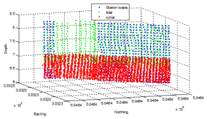
In order to evaluate the performance of the integrated Sonar-LiDAR survey solution proposed by the Interdisciplinary Development Centre for Ocean Mapping (CIDCO) and the Mosaic3D for the inspection and management of its port infrastructures, the Port of Montreal mandated the CIDCO to produce a 3D representation of the wharf faces of sections 54 to 80 and 103.
Taking advantage of a drop in water levels at the Port of Montreal between June 2011 and November 2011, a 2m-by-4m section of Pier 55 of the Port of Montreal was scanned using a Robotic Total Station to create a reference grid of 740 uniformly distributed control points. The topographic and bathymetric point clouds acquired using the LiDAR-Sonar system evaluated here are then compared to this reference grid to derive the uncertainty.
The uncertainties obtained for each point cloud (LiDAR, sonar and combined) are presented in the table below.
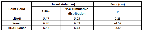
Systematic error is also shown. A negative value means that the point cloud is in front of the reference. The sonar therefore tends to underestimate its distance from the dock and the LiDAR tends to overestimate it.
Since the customer is aiming for an uncertainty of 5 cm (95% CI), it seems necessary to process the scatterplot to reduce the standard deviation. The CUBE algorithm implemented in Caris-HIPS would probably give good results, but the software does not yet support surface projections on a vertical plane. However, a simpler in-house algorithm could be implemented quite easily and would probably meet the specifications.
Comparative study diver inspection vs MBES
Year: 2012
Partner: AxSub
Theme: Deployment strategies
Hardcover Publication: Diver-MBES_Internal Report_2012
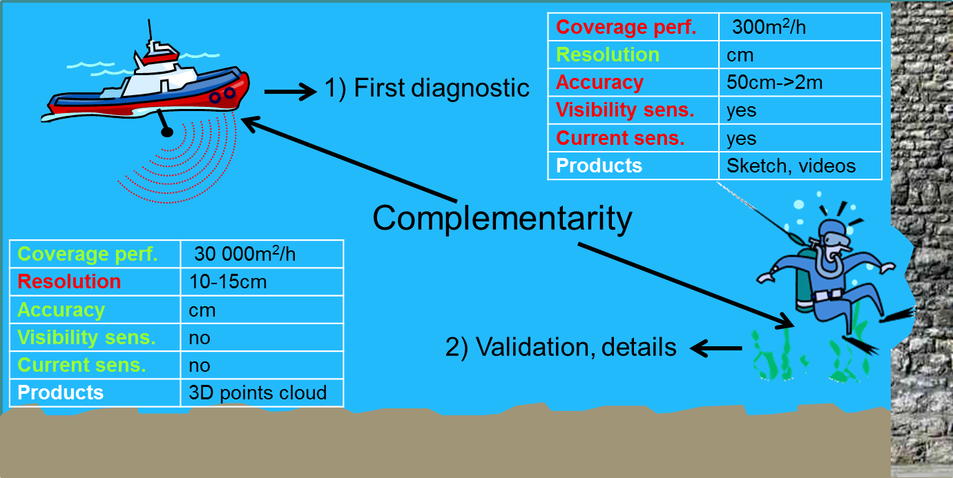
It has been shown that remote inspection technologies and traditional dive inspection are complementary. Remote inspection demonstrates high coverage, good accuracy and insensitivity to visibility and current. Diving inspection stands out for its high-resolution power.
Prototype for generating vertical surfaces
Year: 2013 -> 2015
Partners: Port of Montreal / Teledyne Caris
Theme: Value-added products
Related Publications: Leblanc_Caris_2012 ; Rondeau_USHydro_2015
In 2013, CIDCO developed a prototyped data processing tool specially adapted for vertical surfaces whose aim allows work on surface models (2D1/2) with an arbitrary orientation. This tool thus allows to model and analyse finely vertical wall models, and to carry out deformation maps in relation to a reference surface (civil engineering plan, survey measurements of the aerial part of the structure).
This prototype was taken up and integrated into the Engineering Analysis Module of Caris BaseEditor in 2014 thanks to financing from the Port of Montreal. It was presented jointly by Caris and CIDCO at the USHydro15 conference.
This module concretizes 3 years of work conducted at CIDCO to promote the relevance of offering infrastructure managers as well as engineers the possibility to produce from a 3D point cloud a vertical surface model to facilitate the analysis of deformations of an immersed structure.
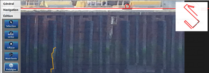
Development of the GeoSketch application
Year: 2013 -> today
Partners: Port of Montreal / Sygif International
Theme: Deployment strategies
Related Publications: GeoSketch_Internal Report_2013
With GeoSketch-Port, the inspector can replace his sheet of paper with an electronic tablet and his measuring tape with a rectified image. The procedure is simple:
- Take a photograph. Upon arriving at the area, the inspector uses the photographic camera built into his electronic tablet to take a picture of the surface to be inspected.
- Rectify the shot. The powerful rectification engine, supported by the GeoSketch software kernel, allows the inspector to correct the perspective effects of the shot and to scale his image in a few clicks.
- Make the drawing. The inspector can then use the rectified image to make his inspection drawing. He can take measurements (the rectified image being to scale), add comments on the drawing directly or specifically for a particular break.
- Export the drawing. The drawing is available in DXF format directly for later use in CAD software if required.
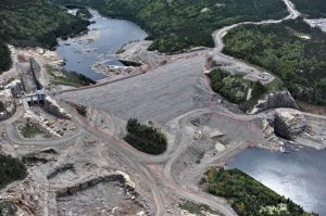
Romaine-2 River dam wall survey
Year: 2014
Partners: IREQ (robotics group)
Theme: Data quality
Related Publications: Stoeffler_CDA_2015 ; Croteau_CIDCO_2015
Hydro Québec wanted to carry out a validation study of a numerical method for calculating the deformation of the Romaine 2 structure in different mechanical loading configurations (empty dam, half-filled dam, and filled dam at its operating rating).
In addition to the implementation of various survey systems (LiDAR, MBES), the level of accuracy required to monitor the deformation of the Romaine 2 dam poses a number of problems that are not part of standard hydrography. Indeed, the level of accuracy and measurement precision expected here is very high.
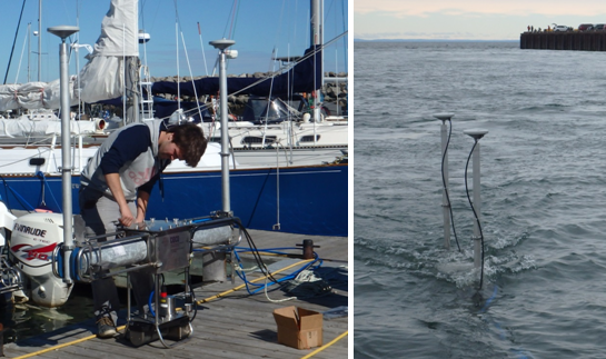
MBES (surface) vs BV5000 (bottom)
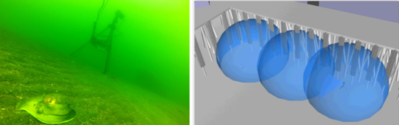
On the left, BV5000 being acquired on its tripod at the bottom of the water. On the right, the 3 spheres represent the maximum volume inspected by the BV5000 on 3 different stations.
Year: 2014
Partners: internal study
Theme: Deployment strategies
It is relatively clear that acoustic sensors of the BV5000 type can obtain images of detail that cannot be achieved by surface multibeam. However, two essential problems remain a hindrance to their use:
- Difficulty and time of implementation (tripod deployment, need for targets);
- The treatment of control points and the treatment of point clouds ("surface matching");
- The georeferencing of the scene in an absolute geodetic reference frame.
Surface systems have the advantage of allowing rapid surveys of underwater infrastructures and determination of global defects (verticality for example), but their resolution and detection power remains physically limited. Acoustic cameras, when deployed closer to structures, allow point clouds with better resolution and thus detect the presence of relatively small local defects. However, georeferencing and georeferencing of these images remains the main problem and can be very costly in terms of deployment time.
ULS500
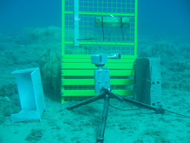
Deployment of a ULS500.
Year: 2014
Partners: 2GRobotics / Park Canada
Theme: Deployment strategies
Related Publications:
The objective of the project was to determine the limitations of use and/or advantages of underwater lasers compared to acoustic systems, in different contexts of use: mounting on mobile vehicles, different environments (especially with regards to turbidity) and different scenarios.
A tripod-mounted ULS 500 was deployed in shallow water (Port of Rimouski). Difficulties arose which were a priori linked to the very high turbidity of the water and the light conditions of the bottom. The ULS is a system that triangulates the reflections of a green laser using a CCD camera whose relative orientation with respect to the laser source is well known. Thus, the image received by the CCD camera (which contains the points corresponding to the impacts of the Laser on the areas of high reflectance in relation to the ambient water) allows to geolocate the detected points relative to the local reference mark of the ULS. The main difficulty encountered was the high turbidity during the tests in port (Rimouski) and river (Lyon, France) areas. The conclusion of these tests was negative with regard to the use of ULS in turbid areas. As the majority of the structures subject to inspection work are located in turbid environments, it appears that this technology should be discarded.
Comparative study between 3 MBES
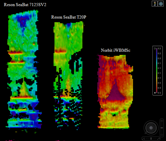
Comparison of the detection capacity of three multi-beam echosounders on the Rimouski reference wall.
Year: 2015
Partners: SeaHorse Geomatic, Teledyne Reson
Theme: Data quality
A question often asked by infrastructure managers and engineers in relation to an inspection system is: "What is the size of the smallest defect (implied: crack, protrusion) that you are able to detect with this system? ».
Three surface-operated multibeam systems were evaluated in this study:
- The Reson SeaBat 7125SV2 fishfinder
- The Reson SeaBat T20P fishfinder
- The Norbit iWBMSc fishfinder
For each, we measured:
- Smallest linear (vertical) crack detected
- Smallest linear (vertical) protrusion detected
- The smallest hole detected
- The smallest cubic protrusion detected
- Sensitivity to the type of material (wood)
Towed hydrographic carrier
Towed hydrographic plateform on which a Reson Seabat T20P fishfinder is installed.
Year: 2015
Partners: UQAR Chaire en Génie de la Conception
Theme: Deployment strategies
Related Publications: Rondeau_TMTW_2015
How an inspection system is calibrated and operated has a direct impact on the quality (accuracy, detection capability) and reliability (accuracy of defect positioning) of the data collected.
One of the main challenges in deploying a system in an infrastructure inspection context is the assembly and calibration of the system components on the sounding platform (most often a hydrographic launch). The precise and accurate measurement of the lever arms (sounder/IMU/GPS) and mounting angles (sounder/IMU) is crucial.
In order to simplify and rigorously lock the assembly and calibration phase of the platform, CIDCO proposes the use of a towed hydrographicplatform.
It is dismountable in 5 pieces, to be easily transportable in 2 suitcases, the platform once assembled measures 1.7m long by 0.25m wide by 1.70m high. It consists of a central "hydropod" on which are mounted the multibeam echosounder, the inertial unit and the sound velocity sensor, as well as 2 masts at the end of which are bolted the GPS antennas.
In the context of infrastructure inspection, such a pre-calibrated platform increases deployment reactivity while limiting the associated costs (time saving during assembly, fast transport to site, only need for a small boat of opportunity).
Mechanical tilt vs. electronic tilt
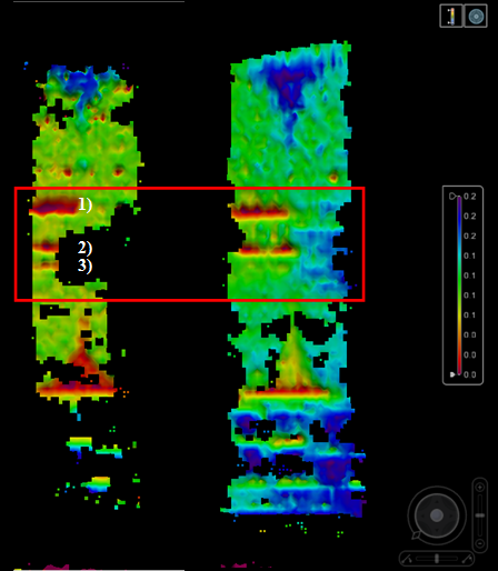
Comparison of detection capability for a mechanically tilted sounder (left) and an electronically tilted sounder (right).
Year: 2015
Partners: internal study
Theme: Deployment strategies
In infrastructure inspection, it is quite natural to want to aim the multibeam sounder at the structure in order to maximize the number of "useful" beams, i.e. those that will impact the structure, so as to increase the detection capability.
Two modes are possible:
- Either the sounder is mechanically tilted, which requires the use of a dedicated mechanical interface and a specific installation;
- Or a feature offered by some multi-beam echosounder is used, which consists in electronically orienting the beams by means of a beam-forming process. The latter solution does not require a mechanical reinstallation of the sounder, so the receiving antenna can remain horizontal.
The mechanical inclination of the sounder allows a clear increase in detection capacity. On the other hand, the dynamic calibration (patch test) of a mechanically tilted sounder is difficult. The conventional methodology of making a line pattern on a flat bottom (roll) and on a slope (pitch, heading) does not allow to solve the sonar/IMU mounting angles finely enough. Angular residuals persist. The dataset is marred by a systematic error.
CIDCO's work on the problem of automatic calibration makes it possible to precisely calibrate the sonar/IMU couple whatever its orientation. Preliminary results obtained on a dataset collected on the wall of the Romaine dam2 show the potential of this approach.
Scour detection and inspection
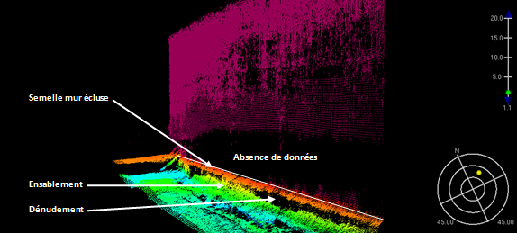
Variable sanding/stripping of the lock wall footing -> validated by the divers. Lack of data at the bottom of the wall -> invalidated by the divers.
Year: 2015
Partners: The St. Lawrence Seaway Management Corporation / WSP Canada
Theme: Deployment strategies
A survey using a Reson SeaBat 7125SV2 multibeam echosounder was conducted on the upstream and downstream sections of the St. Lambert lock (Montreal area). The main objective of this survey was to provide the engineer in charge of the project with a general assessment of the condition of the structure in order to optimize the inspection dives. Analysis of the bathymetric dataset conducted on site the day following the survey (after data pre-processing) identified four potential scour zones for the downstream section and five for the upstream zone. Divers conducted check dives on these areas only.
Most of the targets identified in the sonar point cloud were relevant and the intervention of the dive team could thus be optimized.
However, we notice a lack of data at the bottom of the wall on some sections that the dives could not really explain. This is probably the result of a wedge effect (multi-path). The "multi-detect" mode for Reson echo sounders seems to correct some of this aberration. This mode was not used during the St. Lambert Lock survey.
Inspection by ASV
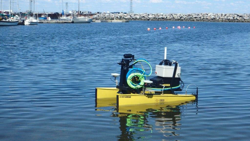
Use of a CataRob ASV to carry out an inspection survey at the Rimouski marina.
Year: 2016
Partners: PingDSP; Applanix
Theme: Deployment strategies
A CataRob ASV has been modified to carry a PingDSP interferometric sonar.